Getting PWM to Work on my TI SimpleLink Board (CC13xx)
So I finally got PWM working on my TI SimpleLink MCU, when I first started, I kept seeing “PWM” all over the datasheets and motor control examples, and to be honest, it was a bit confusing? Like, I knew it was for controlling stuff like motors and LED brightness, but actually getting the code to run was a different story.
After a bunch of trial and error (and yes, a few failed projects), I finally got a solid example running. Here’s my notes and codes, hopefully it helps you out too.
What is PWM?
PWM means Pulse Width Modulation.
It’s a digital signal that switches between HIGH and LOW very fast. By changing the ON time (duty cycle), we can control power delivered to a load like motor, LED, or fan.
Think of a LED:
- 0% duty cycle – It’s completely off.
- 50% duty cycle – It’s at half brightness.
- 100% duty cycle – It’s fully on, bright as can be.
It’s a smart trick used by microcontrollers to simulate an analog voltage using a digital pin.
So, basically, PWM controls average voltage over time by controlling how long a signal stays ON in each period.
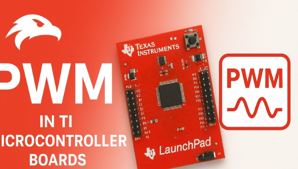
The TI SimpleLink MCUs I Used
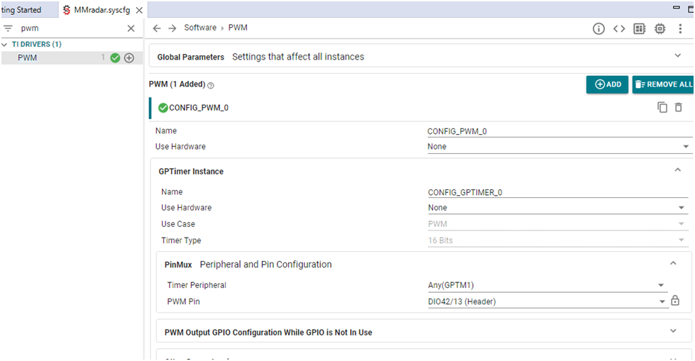
I was working with the TI SimpleLink family, which has chips like the CC1354P10, CC2642R, CC3235S, CC1312R, and others. They are marvelus for low-power and wireless IoT stuffs. The best part is TI gives this SysConfig tool it can be used to config the in-built drivers for PWM, UART, ADC, SPI, I2C. You basically just click around to set up your gpio pins and peripherals, and it writes a bunch of the configuration code. Saves a ton of time and are supported by TI-RTOS (SYS/BIOS) operating system.
TI provides SysConfig tool, where you can just a click, select pins and peripherals (like PWM), and it auto-generates all driver configuration headers for you.
Hardware Setup
For this experiment, I used:
| Component | Description |
|---|---|
| Board | TI CC1354P10-1 LaunchPad |
| Power | USB (5V from PC) |
| Pin | CONFIG_PWM_0 (selected in SysConfig) |
| Output | LED or external pin to measure PWM |
| Tools | Code Composer Studio (CCS) + SysConfig |
Software Setup
- Open Code Composer Studio (CCS), If you don’t have it already, you can grab it from TI’s website.
- Create a new TI-RTOS project for your SimpleLink MCU.
- Open SysConfig → Enable the PWM by clicking Add button.
- Set one PWM channel (example: CONFIG_PWM_0).
- Build and flash the program.
The Code Part
Here’s the code that worked for me. It makes an LED Glow between half brightness and full brightness.
// ============================================================================
// | PWM | Meaning |
// | ——– | ————————————– |
// | y_max | set max y for accuracy |
// | duty_max | Signal time period |
// | dutyValue| PWM initial duty |
// | duty | PWM Output Value 0% to 100% 0–1*1000 |
// | Info* | Max PWM Volt 3.3v |
// ============================================================================
#include <ti/drivers/PWM.h> // Include TI PWM driver
#include <stddef.h> // For standard definitions
#include <stdint.h> // For fixed width integers
#include <stdbool.h> // For boolean data types
#include <string.h> // For string operations if needed
/* TI-RTOS Header files */
#include <ti/sysbios/BIOS.h> // TI-RTOS BIOS header
#include <ti/sysbios/knl/Task.h> // TI-RTOS task management
/* Driver Header files */
#include <ti/drivers/GPIO.h> // GPIO driver for pin control
#include <ti/drivers/UART2.h> // UART driver for debug (optional)
/* Driver configuration header (auto-generated by SysConfig) */
#include “ti_drivers_config.h” // Contains pin and peripheral mappings
// ============================================================================
// Global Variables and Constants
// ============================================================================
static PWM_Handle pwmHandle; // Handle for PWM instance
static PWM_Params pwmParams; // Structure to hold PWM parameters
static uint32_t pwmPeriod_us = 1000; // PWM period = 1ms → 1kHz frequency
uint16_t y_max = 2500; // Max Y value for scaling/accuracy
uint16_t duty_max = 1000; // Max duty value (same as period for 100%)
uint16_t volt_max = 3300; // Reference voltage (3.3V in mV)
// ============================================================================
// Function: PWM_initOutput()
// Purpose : Initialize and start PWM output
// ============================================================================
void PWM_initOutput(void)
{
PWM_init(); // Initialize the PWM driver
PWM_Params_init(&pwmParams); // Load default PWM parameters
pwmParams.dutyUnits = PWM_DUTY_US; // Duty unit in microseconds
pwmParams.periodUnits = PWM_PERIOD_US; // Period unit in microseconds
pwmParams.periodValue = pwmPeriod_us; // Set PWM period (1kHz)
pwmParams.dutyValue = 0; // Start with 0% duty (OFF)
// Open PWM channel (configured in SysConfig as CONFIG_PWM_0)
pwmHandle = PWM_open(CONFIG_PWM_0, &pwmParams);
if (pwmHandle == NULL)
{
while (1); // Halt here if PWM fails to open
}
PWM_start(pwmHandle); // Start generating PWM signal
}
// ============================================================================
// Function: PWM_setDutyFromValue()
// Purpose : Set PWM duty based on input value (0 → 100%)
// ============================================================================
void PWM_setDutyFromValue(uint16_t inputVal)
{
uint32_t duty = inputVal; // Copy input to local variable
if (duty > pwmPeriod_us) // Check upper limit
duty = pwmPeriod_us; // Clamp duty to 100% if exceeded
PWM_setDuty(pwmHandle, duty); // Apply duty to PWM output
}
// ============================================================================
// Function: mainThread()
// Purpose : Main application task
// ============================================================================
void *mainThread(void *arg0)
{
GPIO_init(); // Initialize GPIO driver
PWM_initOutput(); // Initialize PWM output channel
while (1)
{
PWM_setDutyFromValue(500); // Set PWM to 50% duty cycle
Task_sleep(1000 * 100); // Wait for some time (adjust speed)
PWM_setDutyFromValue(1000); // Set PWM to 100% duty cycle
Task_sleep(1000 * 100); // Wait again
}
}
Working of Code
PWM_initOutput(): This function gets the PWM peripheral all ready to use. It tells the driver what units we’re using (microseconds) and sets the initial period and duty cycle.PWM_setDutyFromValue(): This is a handy function I made to change the brightness level. Just give it a number between 0 and 1000 (for 0% to 100%).- The
while(1)loop: This is where the action is. It just keeps switching the LED between half-bright and full-bright each second.
Conclusion
PWM is a very simple but very powerful technique for variable outputs.
With just few lines of code, we can control the motor speed, LED brightness, or even generate analog like signals from digital outputs.
TI’s SimpleLink MCU family makes it much easier by providing a ready drivers and configuration tools.
Once you understand how to use PWM_init, PWM_setDuty, and SysConfig, you can handle many real-world projects with full control.