When we are working with TI MCUs like CC1354P10, CC1310 or any LaunchPad series, the first thing we do after setting up the project is make the LED blink, it just to confirm that everything is working fine.
But after that, we want to see something more on the serial terminal, right? That’s where UART debugging comes in handy, UART is a communication protocol which uses RX and TX 2 wire setup.
In this post, I’m sharing my simple example program used in TI CC13xx family LaunchPad MCU’s where I blink two LEDs and send a small text message through UART every time the LED toggles and receive the message in PC through USB TTL module. It’s kind of a heartbeat test to check both GPIO and UART are alive.
Hardware Setup Notes
- Config GPIO for LED’s, If the default LED avail in MCU Board to config in (Uses Hardware)
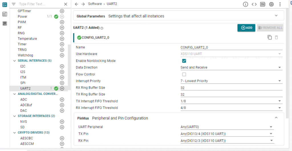
- TX and RX pins are assigned automatically when you are add the UART from your TI SysConfig file (you can verify it under
CONFIG_UART2_0inti_drivers_config.h). - If you’re using CC1354P10 LaunchPad, usually TX = DIO13 and RX = DIO12.
- Don’t forget to connect GND to your USB-to-Serial (USB-TTL Converter) adapter if you’re using external UART.


Why its useful
This example is more powerful than it looks:
- Timing Check: The consistent blink helps you visually verify task timing and delays.
- Non-Invasive Debugging: It’s a much better alternative than constantly halting the processor with breakpoints, especially when you’re debugging timing-sensitive code.
- UART Foundation: This is no-fuss starting point for more complex UART projects like talking to sensors, implementing Modbus protocol, or even sending MQTT through messages.
Overview
This program does:
- Initializes GPIOs for LEDs.
- Initializes UART for serial communication (115200 baud or 9600).
- Enters a infinite loop where the LEDs blink alternately in 2 sec once.
- Print the txt messages like “Toggle LED 0” and “Toggle LED 1” on UART Serial Monitor each time the LEDs change.
Source main.c
#include <ti/drivers/GPIO.h>
#include <ti/sysbios/knl/Task.h>
#include "ti_drivers_config.h"
#include <string.h>
#include <ti/drivers/UART2.h>

// Let's define a comfortable blink delay (2 seconds with a 10us tick)
#define BLINK_DELAY_TICKS 200000

UART2_Handle uart0; // Our handle to the UART

// Quick function prototypes
void Write_0(const char *str);
void UART_debug_init(uint32_t baudRate);

// The main task where the magic happens
void *mainThread(void *arg0)
{
    // Step 1: Wake up the drivers
    GPIO_init();
    UART_debug_init(115200); // Let's go with a standard 115200 baud

    // Step 2: Start with both LEDs off (assuming active-low on LaunchPads)
    GPIO_write(CONFIG_LED_0_GPIO, 1);
    GPIO_write(CONFIG_LED_1_GPIO, 1);

    // Step 3: The main loop - the heartbeat itself
    while (1)
    {
        // Turn on LED1, turn off LED0, and send a message
        GPIO_write(CONFIG_LED_0_GPIO, 1);
        GPIO_write(CONFIG_LED_1_GPIO, 0);
        Write_0("Toggle LED 0\r\n"); // The '\r\n' is for a clean new line in your terminal
        Task_sleep(BLINK_DELAY_TICKS); // Take a nap

        // Now do the opposite
        GPIO_write(CONFIG_LED_0_GPIO, 0);
        GPIO_write(CONFIG_LED_1_GPIO, 1);
        Write_0("Toggle LED 1\r\n");
        Task_sleep(BLINK_DELAY_TICKS);
    }
}

// This function gets our UART port ready for a chat
void UART_debug_init(uint32_t baudRate)
{
    UART2_Params uartParams;
    UART2_Params_init(&uartParams); // Start with default settings
    uartParams.readMode = UART2_Mode_BLOCKING;
    uartParams.writeMode = UART2_Mode_BLOCKING;
    uartParams.baudRate = baudRate;

    // Try to open the UART port (defined in your SysConfig)
    uart0 = UART2_open(CONFIG_UART2_0, &uartParams);
    if (uart0 == NULL)
    {
        // If it fails, let's just hang here. A debugger breakpoint is useful!
        while (1);
    }

    // Send a welcome message to confirm we're online!
    Write_0("Port 0 ready\r\n");
}

// A helper function to make writing strings easy
void Write_0(const char *str)
{
    UART2_write(uart0, str, strlen(str), NULL);
}
What to Expect When You Run It
Flash this in to your board and open a serial terminal (like PuTTY, Tera Term, or the one in Code Composer Studio). Set it to 115200 baud, 8-N-1. You should see this output:
Port 0 ready
Toggle LED 0
Toggle LED 1
Toggle LED 0
Toggle LED 1….
Wrapping Up..
This simple first “blink and talk” trick is my absolute starting point for any new TI and other ARM MCU projects. It’s reassuring, it’s informative, and it’s the moment your board truly works fine.
When you see those LEDs blinking and messages printing, you know your board is alive and talking to you.


