
In embedded systems and the industrial automations, RS485 communication is one of the most standardised protocol are used due to its ability to handle long-distance communication through wired and supports multiple devices (master/slave) on a single bus. If you are looking to integrate RS485 into your project with a Texas Instruments (TI) microcontroller like CC1310, CC1354, CC2000, …. and a USB-to-RS485 converter.
We will be using a TI MCU board (such as the CC1354P10-1 or similar) and a USB-to-RS485 converter to communicate with devices over the RS485 through UART interface. We will cover how to interface with the converter and implement error checking using CRC16 which ensures data loss, and create a working RS485 loopback example.
Why Use RS485 with a USB-to-RS485 Converter?
RS485 is a special way for devices to communicate to each other, especially over long distances. It’s often used in factories, smart meters, sensors, and building systems because it’s very reliable.
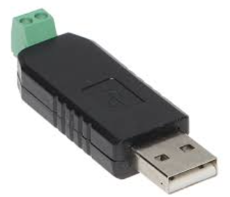
If you want to connect a computer (PC) (or another device with a USB port) to a machine that uses RS485, you can use a USB-to-RS485 converter. This small device helps to communicate each other devices(master/slave), even though they speak different “languages.”
This is useful if your computer or microcontroller doesn’t already support RS485. The converter makes it easy to send and receive data between your device and RS485 machines.
Setting Up the Hardware
The first step is to connecting the hardware components:
- Connect the TI MCU Board:
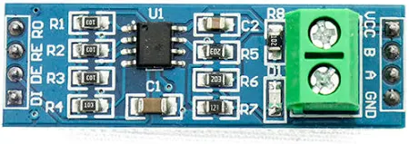
- TX Pin (MCU TX) connects to the RS485 Converter’s A pin.
- RX Pin (MCU RX) connects to the RS485 Converter’s B pin.
- Use GPIO (Driver Enable) to toggle the transceiver between transmit and receive modes if your model needs.
- USB-to-RS485 Converter:
- Plug the USB-to-RS485 converter into your PC or host device.
- This converter will interface with the MCU’s RS485 pins and can be connected to other RS485 devices on the network.
- Power Supply: Ensure that both the TI MCU board and the USB-to-RS485 converter are connected with stable power supply.
How CRC16 Makes Sure Data Is Correct
CRC16 is a method used to check if data was sent correctly, without mistakes. It’s often used in systems like RS485 Modbus, which is common in factories and machines.
how it works:
Before sending data, the system calculates a special number called a CRC checksum using a math formula (hex). This number is sent along with the data like [05 03 02 F5 (8B F3)].
| Byte(s) | Meaning |
| ——- | ————————————– |
| 05 | Slave Address (device #5) |
| 03 | Function Code (Read Holding Registers) |
| 04 | Byte count (4 bytes = 2 registers) |
| 12 34 | Data for register 1 (value = 0x1234) |
|56 78 | Data for register 2 (value = 0x5678) |
| 8B F3 | CRC |
When the other side receives the data, it does the same calculation.
- If the number it gets matches the one that was sent, the data is ok.
- If the numbers don’t match, it means something went wrong during transmission.
This is useful because, during long-distance communication, noise or interference can cause small errors in the data. CRC16 helps catch these errors so the system knows not to trust bad data.
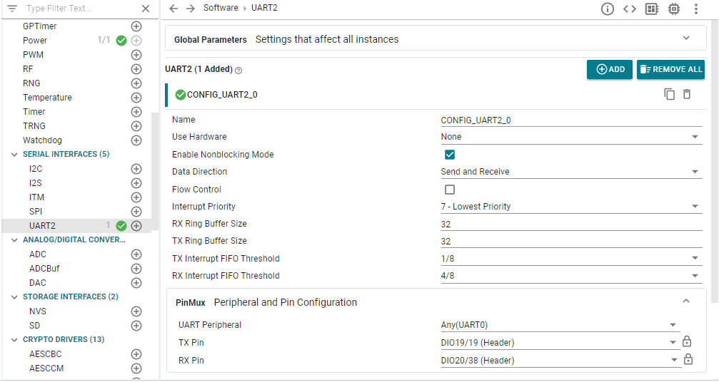
Setting Up the Software
Add the UART in .sysconfig and config the PinMux (TX/RX GPIO PIN SELECTION) and implement the code block.
Breaking Down the Code Block:
let’s look at the actual code that implements the RS485 communication with Modbus.
Step 1: Setup and Initialization
Before we start sending and receiving data, we need to initialize the UART interface and the GPIO pins.
#include <stdint.h>
#include <stddef.h>
#include <stdbool.h>
#include <string.h>

#include <ti/sysbios/BIOS.h>
#include <ti/sysbios/knl/Task.h>
#include <ti/drivers/GPIO.h>
#include <ti/drivers/UART2.h>

#include "ti_drivers_config.h"

#define RS485_DE 21   // DIO21 if your rs485 module no needs to select as dummy pin
Here, we define the essential libraries for GPIO and UART communication. The RS485_DE pin is configured as DIO21, which controls the Driver Enable of the RS485 transceiver.
Step 2: The CRC16 Function
This function calculates the CRC16 Modbus checksum for the data buffer, ensuring that we can verify the data integrity.
uint16_t CRC16_Modbus(uint8_t *buf, size_t len)
{
    uint16_t crc = 0xFFFF;
    for (size_t i = 0; i < len; i++)
    {
        crc ^= buf[i];
        for (uint8_t j = 0; j < 8; j++)
        {
            if (crc & 0x0001)
                crc = (crc >> 1) ^ 0xA001;
            else
                crc >>= 1;
        }
    }
    return crc;
}
How it works:
- The CRC value starts at
0xFFFF. - For each byte in the data, it is XORed with the current CRC value.
- Then, bitwise shifts and conditional XORs based on the polynomial
0xA001are applied to calculate the final CRC value.
Step 3: RS485 Initialization
We need to initialize the RS485 interface, setting the DE pin (DIO21) to LOW initially to configure the transceiver in receive mode.
void RS485_init(uint32_t baudRate)
{
    UART2_Params uartParams;
    GPIO_init();
    UART2_Params_init(&uartParams);

    uartParams.baudRate = baudRate;
    rs485Uart = UART2_open(CONFIG_UART2_0, &uartParams);
    if (!rs485Uart)
        while (1); // UART open failed

    GPIO_setConfig(RS485_DE, GPIO_CFG_OUT_STD | GPIO_CFG_OUT_LOW); // LOW = receive
}
Here to set the UART parameters like baud rate and configure the DE pin for receive mode.
Step 4: Sending Data
To send data, we enable the driver by setting the DE pin high and then transmit the data over UART.
void RS485_send(uint8_t *data, size_t len)
{
    size_t bytesWritten;
    GPIO_write(RS485_DE, 1);   // enable driver
    UART2_write(rs485Uart, data, len, &bytesWritten);
    Task_sleep(1);             // simple delay to finish TX
    GPIO_write(RS485_DE, 0);   // disable driver (receive mode)
}
After sending the data, we disable the driver and switch the transceiver back to receive mode.
Step 5: Handling Received Data
When we receive a data frame, we check its integrity and respond based on the data.
void handleFrame(uint8_t *rxBuf, size_t rxLen)
{
    uint8_t txBuf[32];
    size_t txLen = 0;

    if (rxLen < 5)
        return; // too short

    uint8_t addr = rxBuf[0];

    if (addr != 0x05) // Only address 0x05 accepted
    {
        uint8_t errorMsg[] = {0xEE}; // error code
        RS485_send(errorMsg, sizeof(errorMsg));
        return;
    }

    // Copy address, function code, length
    txBuf[0] = rxBuf[0];  // address
    txBuf[1] = rxBuf[1];  // function code
    txBuf[2] = rxBuf[2];  // data length

    // Swap data bytes (assume 4 data bytes like example)
    txBuf[3] = rxBuf[4];
    txBuf[4] = rxBuf[3];
    txBuf[5] = rxBuf[6];
    txBuf[6] = rxBuf[5];

    // Calculate CRC
    uint16_t crc = CRC16_Modbus(txBuf, 7);
    txBuf[7] = crc & 0xFF;       // CRC low
    txBuf[8] = (crc >> 8) & 0xFF;// CRC high

    txLen = 9;

    // Send response
    RS485_send(txBuf, txLen);

    // Send OK (0x06)
    uint8_t ok = 0x06;
    RS485_send(&ok, 1);
}
We process the received frame, check the address (we only accept address 0x05), swap the data bytes, calculate the CRC, and send a valid response back to the sender.
Step 6: The Main Thread
Finally, the main thread controls the communication loop. It reads incoming data and processes it using the handleFrame() function.
void *mainThread(void *arg0)
{
    RS485_init(9600);
    GPIO_init();
    GPIO_write(CONFIG_DAT, 1);

    const char *startMsg = "RS485 CRC Loopback Ready\n";
    size_t bytesWritten;
    UART2_write(rs485Uart, (uint8_t *)startMsg, strlen(startMsg), &bytesWritten);

    uint8_t rxBuf[16];
    size_t bytesRead;

    while (1)
    {
        bytesRead = 0;
        UART2_read(rs485Uart, rxBuf, sizeof(rxBuf), &bytesRead);

        if (bytesRead > 0)
        {
            handleFrame(rxBuf, bytesRead);
        }
    }
}
The microcontroller waits for incoming data, processes it, and responds with the correct frame.
Conclusion
This setup gives you a solid way to get RS485 communication working using the CC1354P10-1 and other SimpleLink related to TI MCU’s and RS485 MODULE. With CRC16 error checks, it helps make sure your data does not get messed up during transmission.
Whether you are building something for industry or just need long-range communication, this approach is reliable and easy to follow.
If you’re new to RS485 or Modbus, this example is a great way to see how data gets sent, checked, and handled in real devices.
Source RS485.c
Using CC1354 TI LaunchPad with MAX485 Module, You can use either MAX485 TTL-TO-RS485 MODULE or USB TO RS485 MODULE instead of MAX485.
/*
* RS485 CRC Loopback Test – TI MCU [SimpleLink] + RS485 MODULE
* TX = DIO19, RX = DIO20, DE/RE = DIO21
*/
#include <stdint.h>
#include <stddef.h>
#include <stdbool.h>
#include <string.h>
/* TI-RTOS Header files */
#include <ti/sysbios/BIOS.h>
#include <ti/sysbios/knl/Task.h>
/* Driver Header files */
#include <ti/drivers/GPIO.h>
#include <ti/drivers/UART2.h>
/* Driver configuration header (from SysConfig) */
#include “ti_drivers_config.h”
/* RS485 DE pin */
#define RS485_DE 21 // DIO21
UART2_Handle rs485Uart;
/—————- CRC16 (Modbus) —————-/
uint16_t crc16_modbus(uint8_t *data, uint8_t len){
uint16_t crc=0xFFFF;
for(uint8_t i=0;i>1)^0xA001;
else crc>>=1;
}
}
return crc;
}
/—————- RS485 Init —————-/
void RS485_init(uint32_t baudRate){
UART2_Params uartParams;
GPIO_init();
UART2_Params_init(&uartParams);
uartParams.baudRate=baudRate;
rs485Uart=UART2_open(CONFIG_UART2_0,&uartParams);
if(!rs485Uart){while(1);} // UART open failed
GPIO_setConfig(RS485_DE,GPIO_CFG_OUT_STD|GPIO_CFG_OUT_LOW); // LOW=receive
}
/—————- RS485 Send —————-/
void RS485_send(uint8_t *data,size_t len){
size_t bytesWritten;
GPIO_write(RS485_DE,1); // enable driver
UART2_write(rs485Uart,data,len,&bytesWritten);
Task_sleep(1); // small delay
GPIO_write(RS485_DE,0); // back to receive
}
/—————- Main Thread —————-/
void *mainThread(void *arg0){
const char *startMsg=”RS485 CRC Test Started\n”;
size_t bytesWritten;
RS485_init(9600);
UART2_write(rs485Uart,(uint8_t *)startMsg,strlen(startMsg),&bytesWritten);
uint8_t rxBuffer[256];
while(1){
    size_t bytesRead=0;
    UART2_read(rs485Uart,rxBuffer,9,&bytesRead); // read 9-byte frame
    if(bytesRead==9){
        uint16_t crc=crc16_modbus(rxBuffer,7); // CRC of first 7 bytes
        uint8_t txFrame[9];
        txFrame[0]=rxBuffer[0];
        txFrame[1]=rxBuffer[1];
        txFrame[2]=rxBuffer[2];
        txFrame[3]=rxBuffer[4];
        txFrame[4]=rxBuffer[3];
        txFrame[5]=rxBuffer[6];
        txFrame[6]=rxBuffer[5];
        txFrame[7]=crc&0xFF;
        txFrame[8]=crc>>8;
        RS485_send(txFrame,9); // echo with CRC
    }
    Task_sleep(10);
}
}